Diagrams
The System Design Editor provides an interactive canvas tailored for architectural modeling, multi-tier system visualization, and technical presentations. It combines the familiar drag-and-drop ergonomics of tools like Draw.io with deep architectural primitives, hierarchical sub-diagrams, and dynamic presentation scenarios.
1. Canvas & Modeling Basics
The editor is designed for rapid, low-friction diagramming with zero configuration.
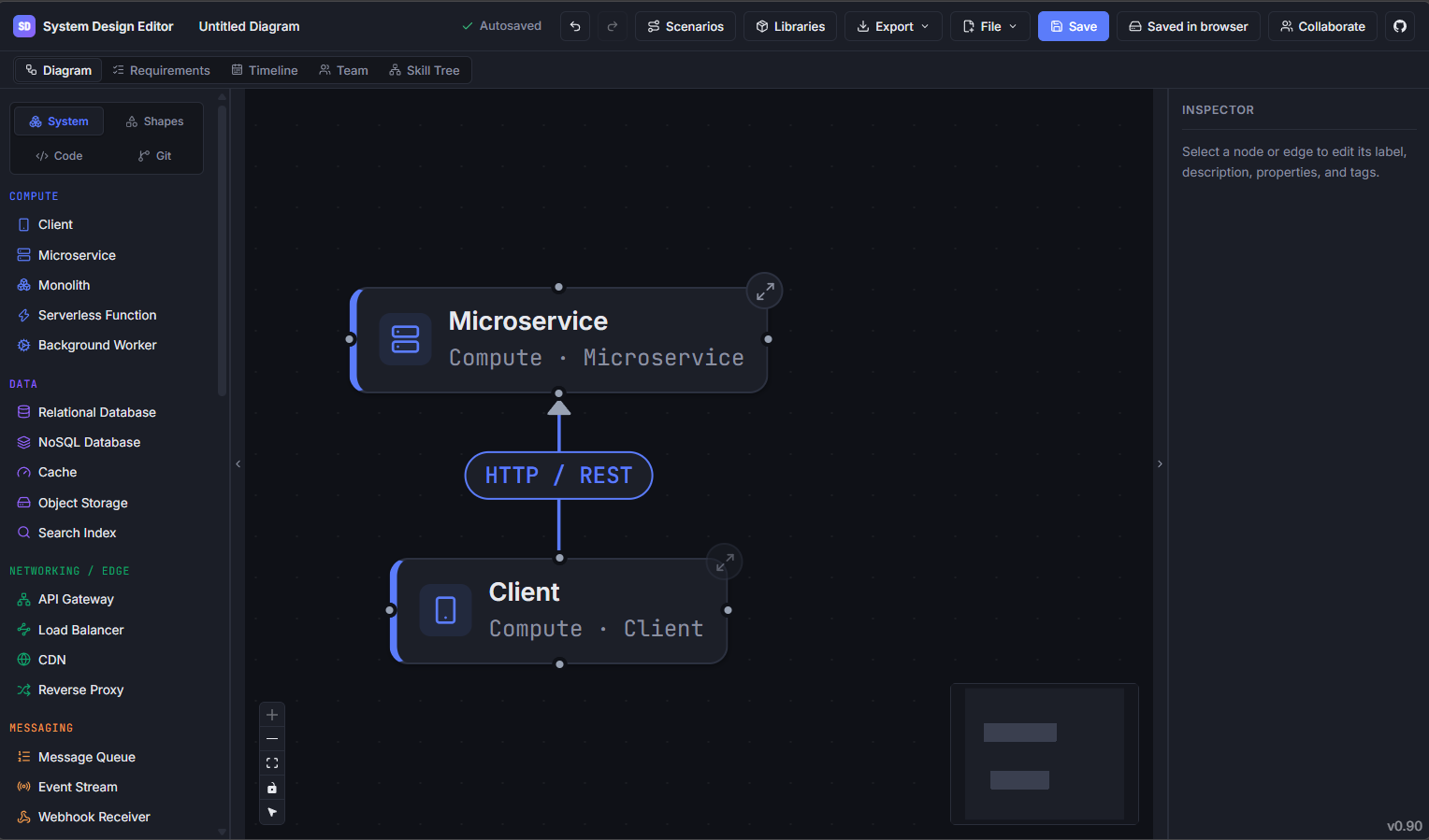
Adding Components & Shapes
- Palette: Drag nodes and components directly from the left sidebar onto the canvas.
- Architectural Nodes: Choose from pre-configured system components (Microservices, Databases, Caches, Gateways, Message Queues, Clients, and Compute nodes).
- Geometric Shapes: Insert standard geometric shapes (Rectangles, Rounded Rectangles, Cylinders, Diamonds, Hexagons, and Cloud boundaries) for custom flowcharts and structural grouping.
- Annotations & Snippets: Add text callouts, sticky notes, and formatted code snippets to document decisions in-place.
Connecting & Routing Edges
- Handles: Hover over any node boundary and drag from connection handles to link elements.
- Edge Types & Styles: Customize connection pathways as directional, bi-directional, solid, dashed, or dotted.
- Waypoints: Click and drag mid-points on connection lines to insert bends and cleanly route edges around intervening components.
- Flow Direction: Set edge flow semantics, which dynamically drive data-flow animations during scenario playback.
Inspection & Customization
Select any component or edge to open the Inspector Panel on the right:
- Labels & Descriptions: Provide human-readable titles and markdown descriptions.
- Icon Overrides: Choose from the bundled Lucide icon catalog to match your exact technology stack.
- Visual Styling: Customize node accent colors, border styles, and Z-index layering.
- Custom Properties & Tags: Attach arbitrary key-value metadata and tags for categorizing systems.
- Requirement Linking: Bi-directionally link diagram elements directly to engineering requirements for traceability.
2. Hierarchical Sub-Diagrams (Drill-Down)
Complex systems quickly become unreadable when flattened onto a single canvas. The sub-diagram engine allows you to model high-level architectures at the root while encapsulating low-level implementation details in nested layers.
How to Use Sub-Diagrams
- Creating a Sub-Diagram:
- Select any architectural node on the canvas.
- In the right-hand Inspector panel, click Create sub-diagram → (or Open sub-diagram if one exists).
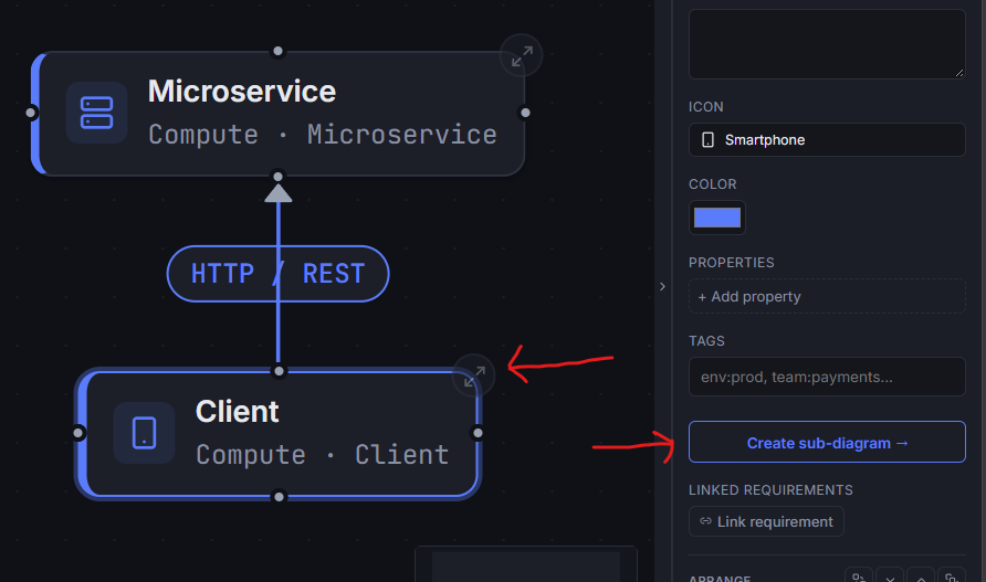
Editing Nested Layers:
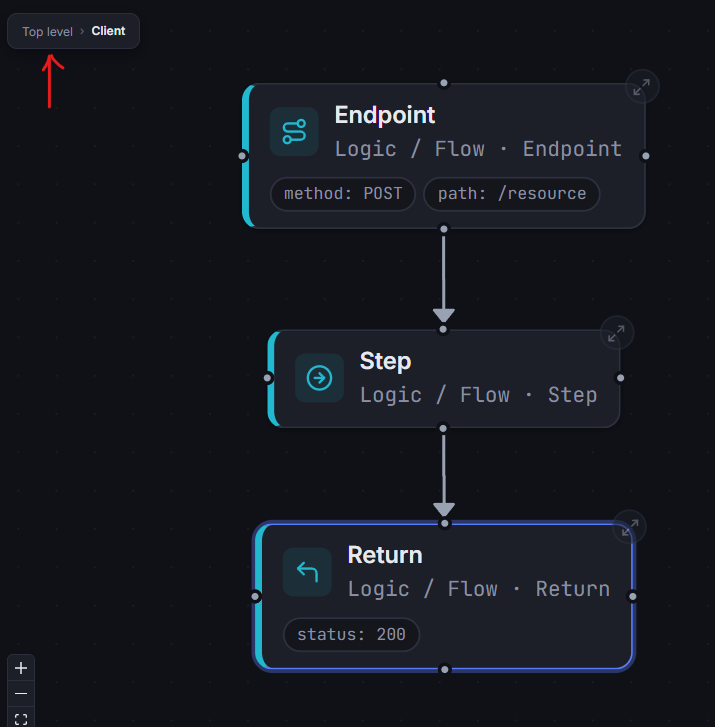
- The canvas transitions into the isolated sub-diagram view.
- Add nodes, edges, and annotations specific to that component's internal architecture.
Breadcrumb Navigation:
- A persistent breadcrumb bar at the top of the canvas (
Root › Service A › Worker Pool) tracks your current abstraction level. - Click any breadcrumb segment to jump directly back to higher levels.
- A persistent breadcrumb bar at the top of the canvas (
- Hierarchy Management:
- Deleting a parent node cleanly cascades and removes its underlying sub-diagram structure.
3. Scenarios & Presentation Mode
Static diagrams often fail to convey runtime execution order, request lifecycles, or failure failover paths. The Scenarios feature turns diagrams into interactive, step-by-step presentations.
Creating a Scenario
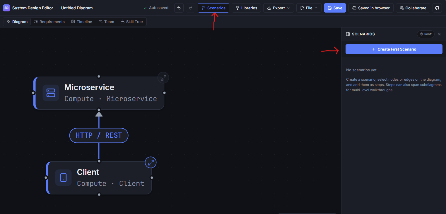
- Click Scenarios (film icon) in the top toolbar or bottom tray to open the Scenario Panel.
- Click + New Scenario and give your scenario a descriptive title (e.g., "User Authentication & Token Refresh Flow" or "Payment Processing with Circuit Breaking").
- Click Add Step to create a presentation sequence. Any selected node and edge wil be added to the step.
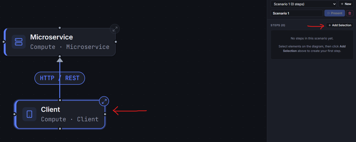
- Click Add Selection to Step to add the currently selected nodes and edges to the step. The selected items will highlight in the diagram to make it clear what would be added.
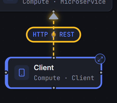
Configuring Scenario Steps
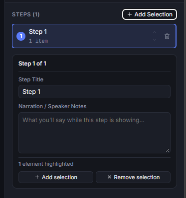
For each step in the sequence:
- Title & Narration: Add an explanatory title and detailed speaker notes / walkthrough narration.
- Focus Elements: Select the nodes and edges involved in this specific step, then click Add Selection to Step.
- Level Context: Steps can span different sub-diagram depths. When stepping into a component, the scenario automatically transitions to the appropriate sub-diagram level.
- Reordering: Use the Up / Down buttons in the step list to adjust sequencing.
Presenting to Stakeholders
Click Present to launch the presentation mode:
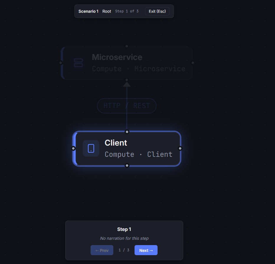
- Targeted Camera Framing: The viewport automatically pans and zooms to frame only the active step's components.
- Atmospheric Dimming: Components outside the current step are dimmed, focusing viewer attention strictly on active pathways.
- Animated Data Flows: Connected edges pulse with animated flow indicators in the configured direction.
- Narrative Overlay: A presentation bar displays step progress (
Step 3 of 8), breadcrumb context, title, and detailed narration. - Controls: Use
← Prev,Next →buttons (or keyboard arrow keys) to step through flows, and pressEscto return to the editor.
4. Linking to Requirements
Architectural components do not exist in isolation; they implement specific functional, performance, and security requirements. The editor enables bi-directional traceability by allowing you to link any canvas node directly to existing engineering requirements.
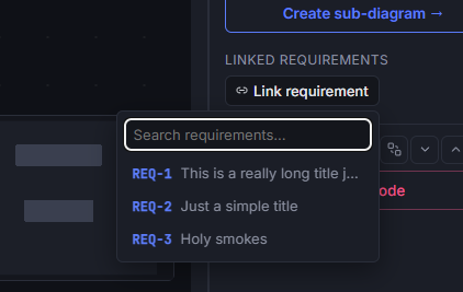
How to Link a Component to a Requirement
- Select a Component: Click any architectural node or shape on the canvas to open the Inspector Panel on the right.
- Open the Linker: In the Inspector panel, locate the Linked requirements section and click + Link requirement.
- Search & Select:
- Type in the search box to filter existing requirements by their ID (e.g.,
REQ-001) or title keywords. - Click any requirement from the dropdown to link it to the selected component.
- The dropdown stays open so you can link multiple requirements in succession.
- Type in the search box to filter existing requirements by their ID (e.g.,
Managing & Navigating Linked Requirements
- Color-Coded Badges: Linked requirements appear as colored pills in the Inspector, reflecting their configured requirement type (e.g., Functional, Security, Reliability).
- Jump to Requirement: Click any requirement pill label to immediately switch to the Requirements View and focus on that requirement's full description, acceptance criteria, and metadata.
- Unlinking: Click the
×button on any pill to remove the link from the component without modifying the requirement itself. - Bi-Directional Traceability: Inside the Requirements View, each requirement card displays its connected diagram components under Linked Diagrams & Components, enabling team members to jump back and forth between design models and specifications.
5. Exporting Diagrams (SVG & PNG)
Diagrams can be exported as standalone vector graphics or high-resolution images for RFCs, wiki pages, presentations, and technical documentation.
Export Formats
| Format | Best Used For | Features |
|---|---|---|
| SVG (Vector) | Web documentation, Markdown wikis, scalable print | Infinite resolution scaling, crisp text, vector paths, small file size. |
| PNG (Raster) | Slide decks, messaging apps, tickets, email reports | High-DPI rasterization, universal image viewer compatibility. |
How to Export
- Navigate to the diagram level you wish to export.
- In the top-right toolbar, click the Export menu.
- Select Download SVG or Download PNG.
- The file automatically downloads using your diagram's document title.
6. Workflow Recommendations
- Start Broad, Then Drill Down: Use the Root level for system boundaries and service communication contracts. Drill down into sub-diagrams for internal class/module interactions or storage schemas.
- Document Edge Semantics: Label connection lines with protocols (e.g.,
gRPC,HTTPS,Kafka Topic) and assign distinct colors to separate synchronous calls from asynchronous event streams. - Pair Scenarios with Requirements: Build scenario walkthroughs to validate acceptance criteria and review implementation flows with team members before coding.
- Export to Markdown: Embed exported SVGs into repository documentation to keep architecture specifications versioned alongside codebase changes.